- Stock: In Stock
- Model: C260.SIM800L
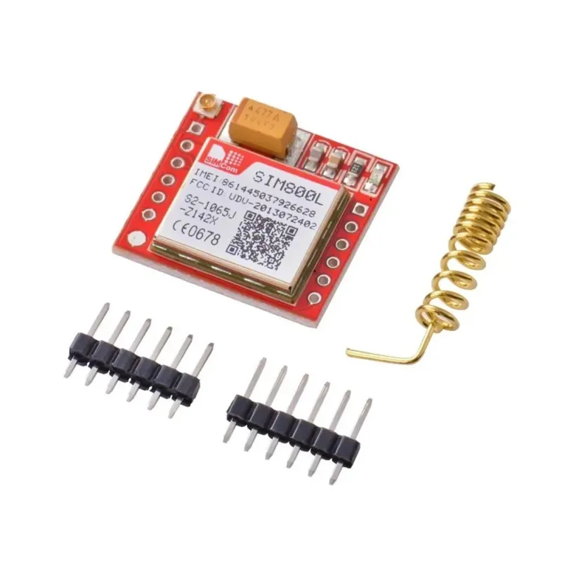
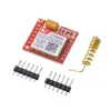
SIM800L GSM/GPRS Module Development Board
The development board with the SIM800L module allows the use of GSM communication and GPRS features with development platforms like Arduino and Raspberry Pi. With this board, you can send and receive SMS, perform location tracking, and even create your own mobile phone. The onboard SIM800L module handles GSM communication and GPRS reception.
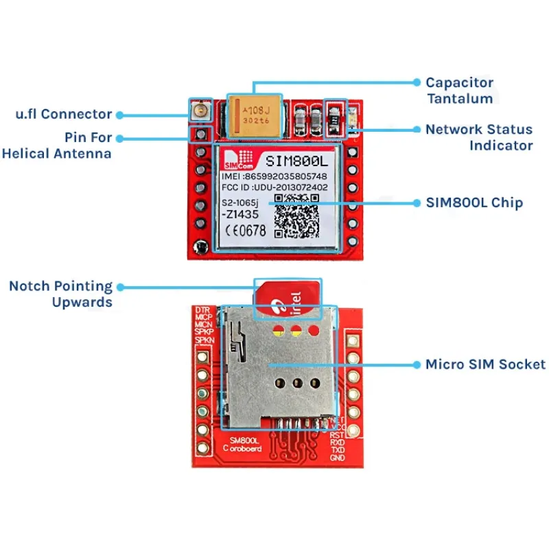
SIM800L is a miniature cellular module that supports GPRS data transmission, SMS messaging, and voice call functionality. Its low cost, compact size, and quad-band support make it an excellent choice for projects requiring long-range communication. Once powered, it automatically searches for and logs into a cellular network. A built-in LED indicates network status:
- Fast blinking: No network coverage
- Slow blinking: Successfully connected
SIM800L GPRS Module Technical Specifications:
- Power supply voltage: 3.8V – 4.2V
- Recommended voltage: 4V
- Power consumption:
- Sleep mode: < 2.0mA
- Idle mode: < 7.0mA
- GSM transmission (average): 350mA
- GSM transmission (peak): 2000mA
- Module size: 25 x 23 mm
- Interface: UART (max 2.8V) with AT commands
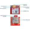
- SIM slot: microSIM (bottom side)
- Supported frequencies: Quad-band (850/950/1800/1900 MHz)
- Antenna connection: IPX
- Status signal: LED
- Operating temperature range: -40°C to +85°C
Important AT Commands:
ATE0 AT+IPR=9600 ATE0&W AT+IPR=0 (for auto baud rate detection)
Sample Arduino Codes:
#include <SoftwareSerial.h>

SoftwareSerial sim800(10, 11); // RX, TX

bool smsSent = false;

void setup() {
  Serial.begin(9600);
  sim800.begin(9600);

  Serial.println("Initializing SIM800L...");
  delay(3000); // Wait a bit for the module to be ready

  // Initialization with AT commands
  sim800.println("AT"); // Start
  delay(1000);
  sim800.println("AT+CMGF=1"); // Text mode
  delay(1000);
  sim800.println("AT+CSCS=\"GSM\""); // Character set
  delay(1000);

  // Send SMS
  if (!smsSent) {
    Serial.println("Sending SMS...");
    sim800.println("AT+CMGS=\"0773329141\""); // ← write your number here
    delay(1000);
    sim800.print("Hello, this is a test message.");
    delay(500);
    sim800.write(26); // Ctrl+Z = 26 (ASCII) → sends the message
    smsSent = true;
    Serial.println("SMS sent.");
  }
}

void loop() {
  // Forward SIM800L responses to Serial Monitor
  if (sim800.available()) {
    Serial.write(sim800.read());
  }
}
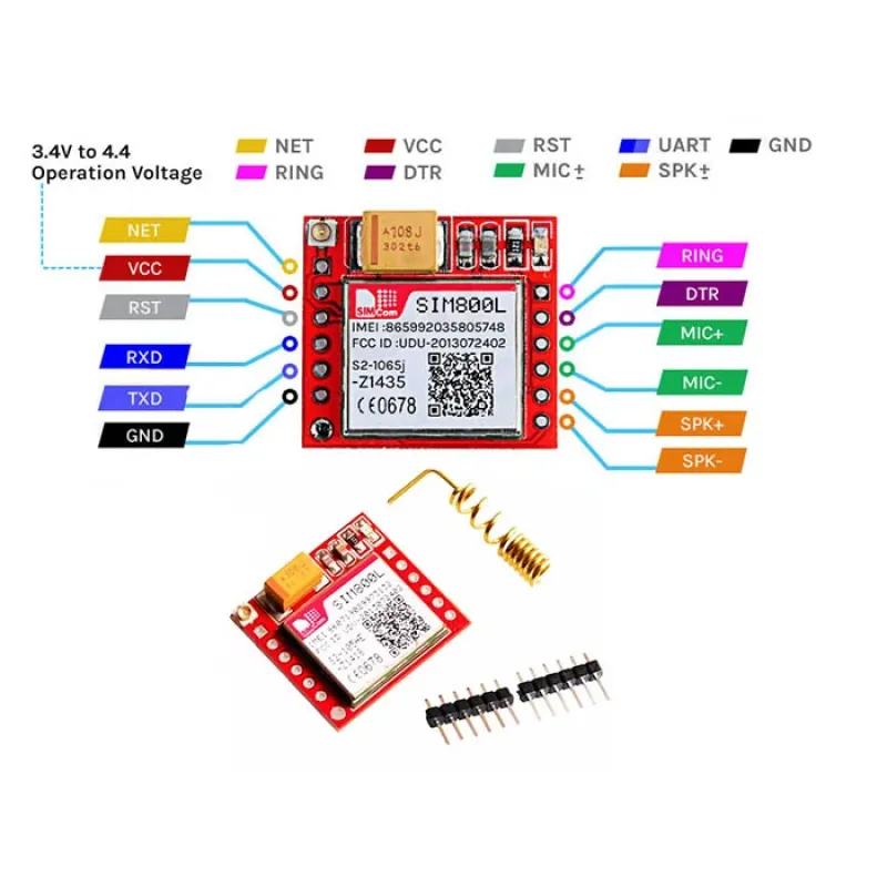
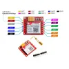
Pinout:
Right Side:
- NET – Antenna
- VCC – Power input
- RESET – Reset
- RXD – Serial receive
- TXD – Serial transmit
- GND – Ground
Left Side:
- RING
- DTR – Sleep mode control
- MICP, MICN – Microphone input (P+ / N-)
- SPKP, SPKN – Speaker output (P+ / N-)
Important Notes:
- Note 1: If the SIM800L module does not respond to AT commands (returns "?"), try changing the Arduino serial monitor baud rate to 115200, reset the module, then use it at 9600 baud.
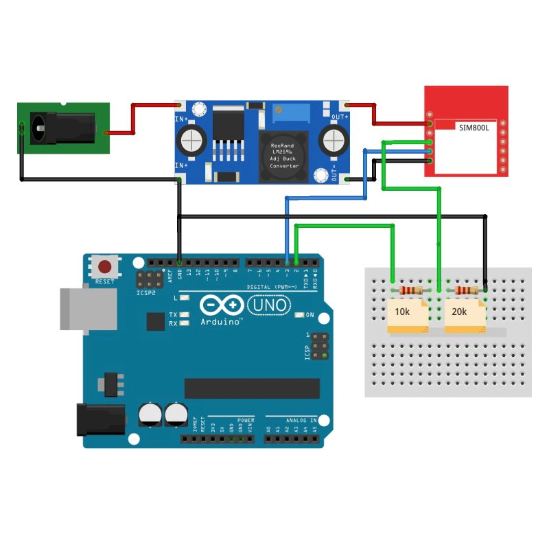
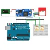
- Note 2: The module draws high current during base station registration. Power supply is critical. If powered directly from Arduino, it may fail to connect. Use a stable voltage regulator like LM2596. The module typically requires 3.7 – 4.2V and up to 2A of stable current. Also, make sure the SIM card PIN code is disabled.


